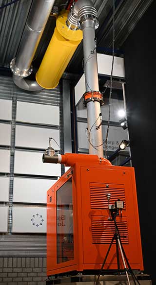
Blower energy performance measurement system up to 750 kW
Energy performance of turbo blowers, screw blowers and multistage centrifugal blowers
Accurately determining the performance of blowers such as turbo blowers, screw blowers and multistage centrifugal blowers. can lead to complex measurement systems. In most cases the energy consumption is the main property to determine. At least the quantities voltage, current, volume flow, pressure, temperature and air humidity must be measured for this. For all measurements applies the more accurate the measurement results must be, the higher the investments and the more critical the application of the instrumentation is required. Our decades of experience in the field of various measurement techniques and our measurement systems for blowers has proven itself. Prior to construction, Sjerp & Jongeneel has set itself the goal of ensuring that the measurement system is transparent and verifiable at all times. In addition, the measurements are extremely accurate and traceable to internationally accepted standards. The measuring system meets the standards for measuring blowers, but explicitly does not hide behind it. After all, these standards are mainly written by blower manufacturers and they have represented their interests in this so that they can maintain their commercial specifications. We will show here that it is not difficult, especially for a technician, to understand our measuring system. This in order to ultimately contribute to the transparency of the actual performance of large energy consumers such as blowers.
Transparent measurement system

Diagram measurement system
A diagram with dozens of measurement points may seem complicated at first sight, but it becomes clear by dividing it into blocks. We consider blowers (DUT,I) that we measure as a black box. The incoming electrical energy versus the outgoing process air is also referred to as wire-to-air efficiency. We therefore measure the volume flow of the air that is actually used. This sounds logical, but the total incoming volume flow is often measured introducing uncertainties when determining the cooling air/process air ratio. On the other hand, we also want for turn-key modules to include all losses for energy consumption. In addition to the blower and motor this includes air filters, EMC filter, frequency converter, control, cooling, internal transport losses and, when applicable, any transmission or oil coolers. The software of the measuring system registers both the external measurements and the internal measurements of the blower module. The measuring system is therefore also used to calibrate the internal sensors of the blower module.
Volume flow
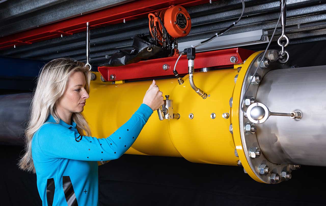
DN400 turbine gas meter
Accurate volume flow measurement of air and gases is challenging due to vortices that can travel hundreds of meters through straight pipework. Obtaining an ideal flow profile is, in contrast to liquids, for air and gas a utopia under non-laboratory conditions. For this measurement set-up, an proven familiar technique has therefore been chosen: the turbine gas meter. Our DN400 turbine gas meter has an integrated flow conditioner and can be dismantled relatively easily and sent to an accredited calibration laboratory. This allows us to perform our volume flow measurements over the entire measuring range with a measurement uncertainty of 0.15%. Calibrated piping is installed at the inlet with a length of 20 x D and exactly the same inner diameter as the DN400 turbine gas meter. This prevents deviations from the volume flow measurements in the system itself.
Properties of air
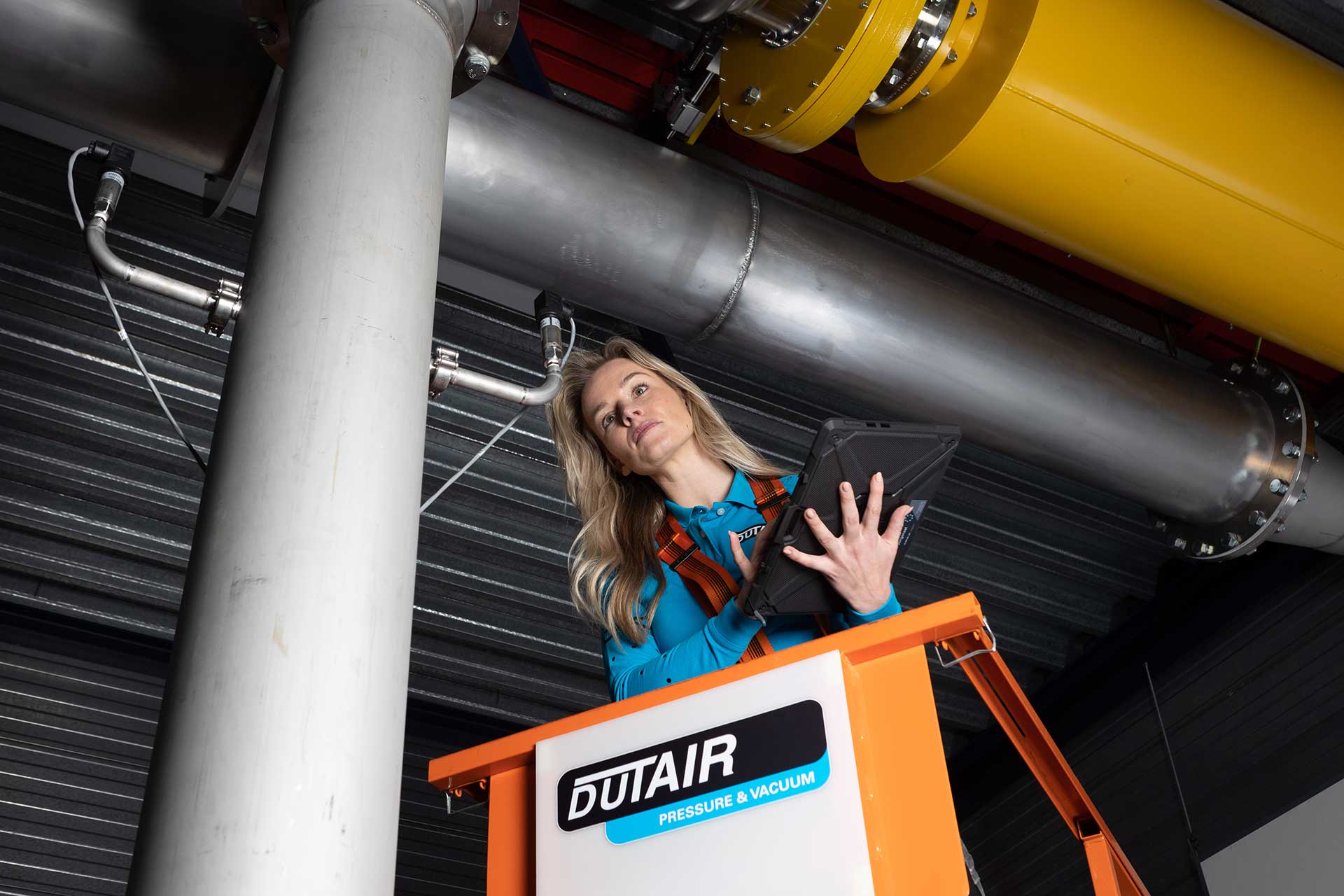
Checking the pressure sensor in the blower outlet path
Air properties is an important element in determining blower performance because of its influence on mass flow and the efficiency of the blowers themselves. At the inlet of the blowers we measure the absolute pressure, temperature and humidity. From these data, the current density of the air and the ratio between water vapour[kg] and dry air[kg] are determined. From this we calculate the humidity ratio W = m(water vapour)[kg] / m(dry air)[kg] of the intake air that does not change in the measurement system. Blowers increase the temperature of the processed air considerably and no condensation will occur. This allows us to use the humidity ratio W, determined at the inlet of the turbine meter, in order to calculate the flow rate very accurately in, among other things, Nm3/h (101.325 kPa & 273.15 K). After the blower, pressure and temperature are measured at various places in the measuring system. These are usually doubled as generous pipe diameters have been used due to the high capacities. The sensors are also placed in such a way that they exceed the existing standards for measuring gases and testing blowers and compressors. In order to guarantee the high accuracy here too, the sensors are thermally separated and are easily interchangeable by means of robust couplings. Also with these quantities it turned out that every manufacturer of measuring equipment has its specialism. In order to achieve the accuracy requested by us, we therefore chose a different supplier for each item to be measured.
Power measurement
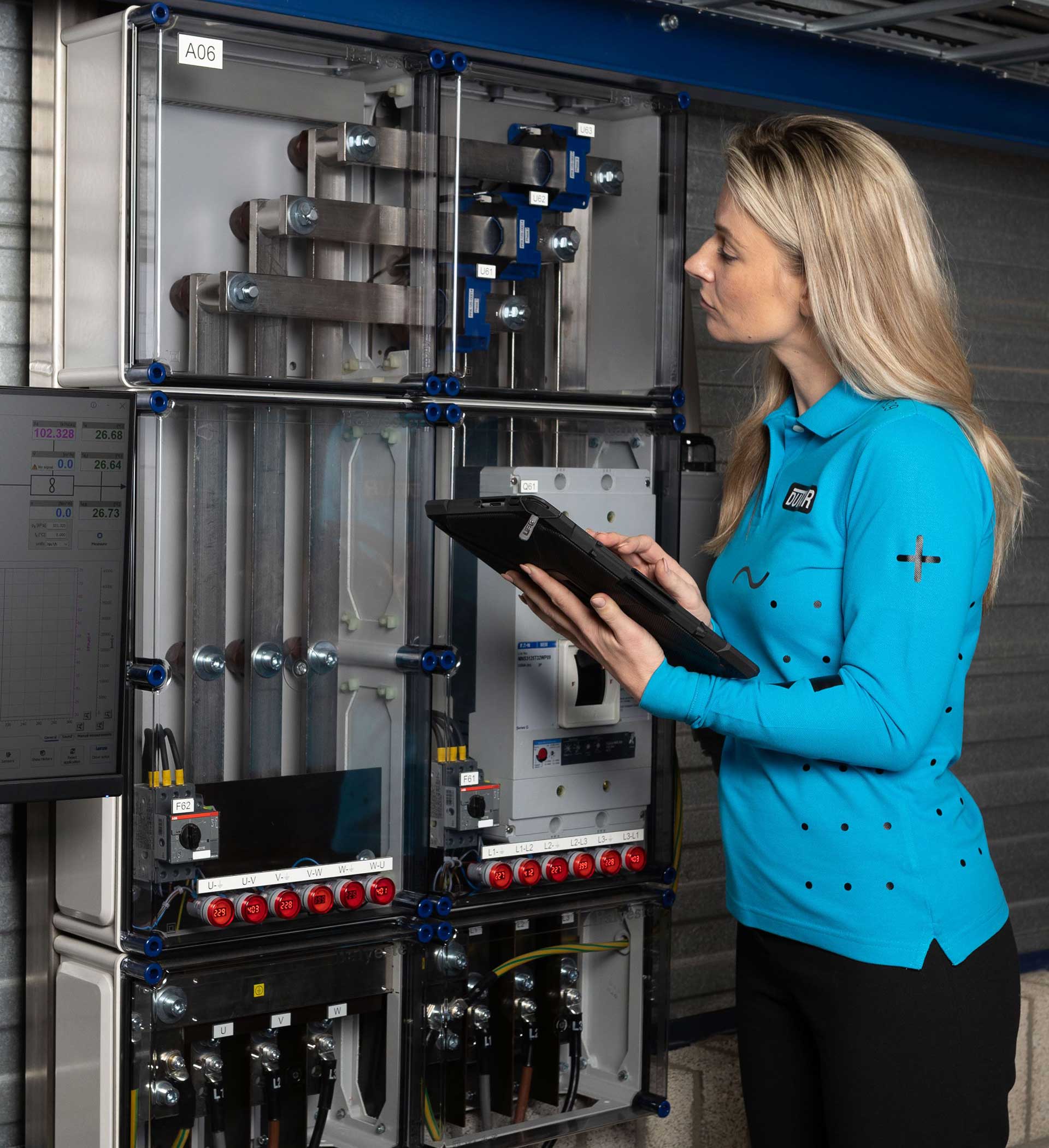
Verifying serial numbers with calibration report of the zero flux current transducers
Turn-key blower modules use variable speed drives. This also means that the current consumed by turn-key blower modules have a large proportion of higher harmonics and therefore also influence the mains voltage. To make accurate power measurements, only power analyzers are suitable here. These are capable of including the high-frequency part in the voltages and currents of all phases. The photo shows the junction cabinet where the 1500 A zero flux current transducers are installed. These are extremely linear over the entire measurement range. The transducers, interface, power analyzer and test leads undergo system calibrations resulting in a measurement uncertainty of 0.05%.
System resistance control
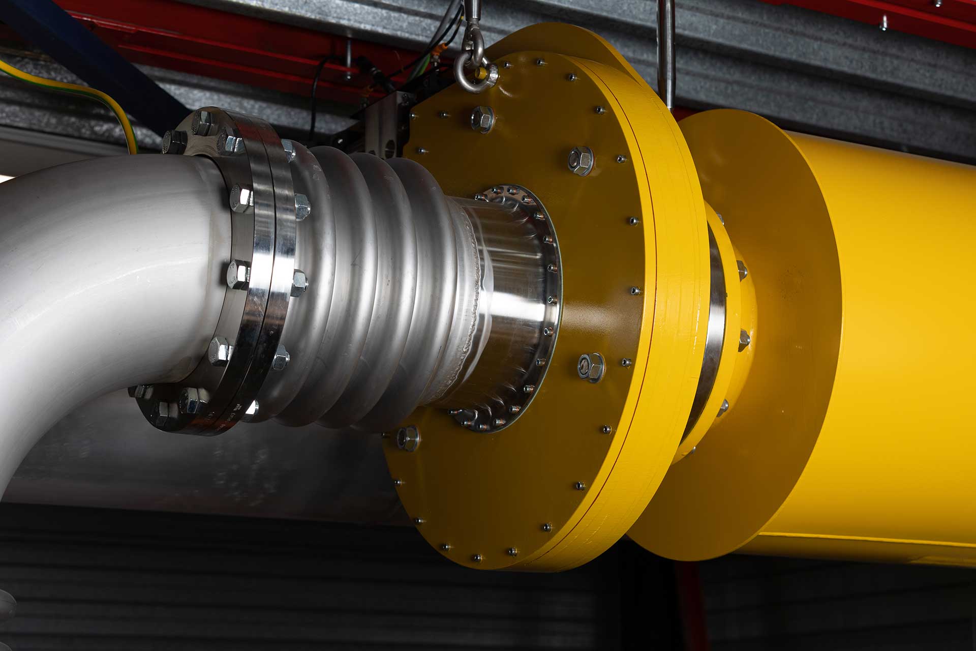
DN250 servo controlled diaphragm valve
The air resistance in the measurement system must be controlled to set and measure the desired stable operating points of blowers. The smaller the steps in which a valve can be controlled open or closed, the closer one can get to the desired operating point. Market research did not lead to a supplier who could achieve the tolerances requested for our measuring system. The DN250 diaphragm control valve shown is a unique in-house successfully developed valve. The external drive is done by means of CNC servo linear technology with which the opening of the valve is controlled in 100,000 steps from 1 to 100%. With turbo blowers, this results to PID control of stable operating points accurate to 1.0 m3/h in practice.
Software
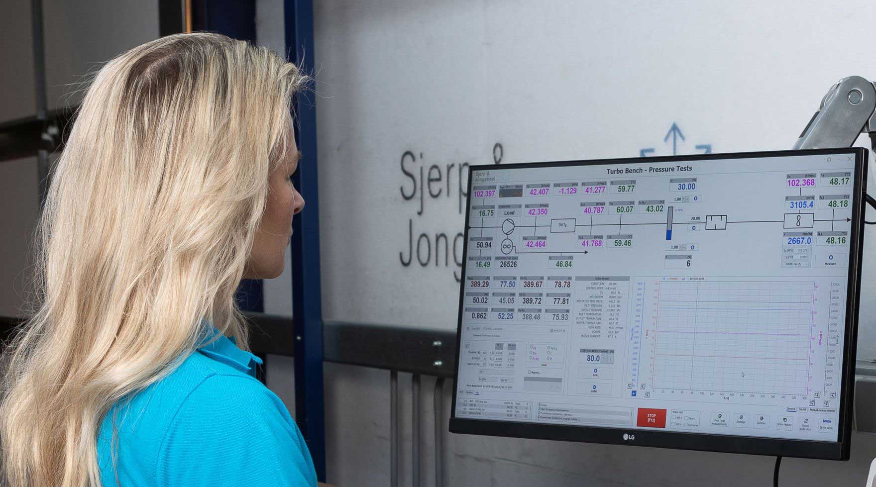
Main screen blower measurement software during stable duty point
The software developed in-house enables us to read and process all measurement data relevant to blowers. In addition, we control turn-key blower modules with it and it contains an extensive PID control with which the desired stable operating points are achieved. The required sensors are described in detail in the sensor database, with the option of adjusting any sensor deviations from accredited calibration reports with multiple correction polynomials. In other words, just like the system calibration for the power measurement, we also capture the entire trajectory for all sensors with a chain calibration. This again with the aim of getting a very accurate reading. The data of all recorded working points can also be traced back to the sensors used and their calibrations. From the database with results, we can generate customized measurement reports with the measured data you want.
Calibration & verification
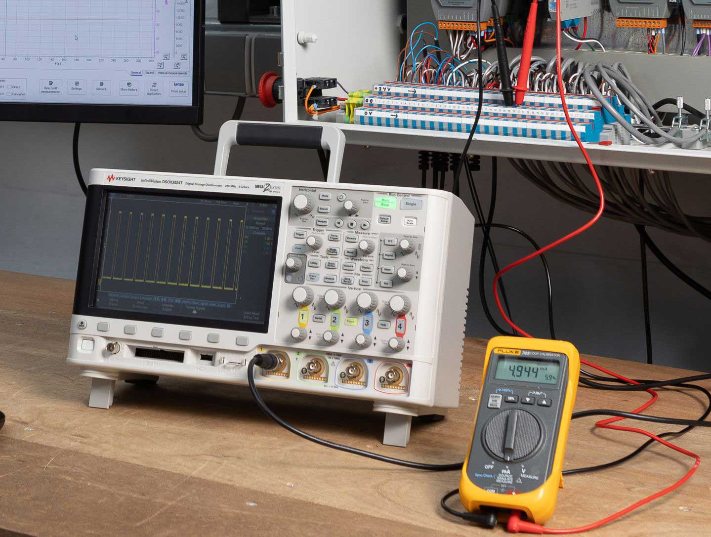
Verification measurement instruments and verification terminal block
With our blower measuring systems, we have set ourselves the goal of taking accurate measurements, traceable to internationally accepted standards and verifiable at any time by third parties. This is important to us because commercial specifications still prevail in the world of blowers and we want to offer our customers realistic, truly traceable blower specifications. This also means that we are currently not telling the best story on the market from a blower-energy-consumption technical point of view. However, we do know that our products are relatively good. So also in terms of energy consumption, with which our blowers can make an important contribution to optimizing processes. We therefore ask you to take a critical look at competitor blower specifications, especially when it comes to energy consumption. This is then also an invitation to do the same with our data. Verification is therefore the basis of our measurement systems. The photo shows how this is possible during live measurements. The DN400 turbine gas meter has two equivalent outputs giving the same number of pulses / m3 / h. One output goes to the measurement system's data acquisition and is processed by the software into display values and stored measurements. The setup in the photo shows a high-frequency oscilloscope with which the other output is measured. Screen values and stored measurements can therefore be compared directly with third-party instruments. This also applies to all other measurements that can be checked with a loop calibrator via the terminal block.


